
Weld quality depends on more than the current setting displayed on a machine. Behind every resistance weld, the relationship between transformer turns ratio, electrical impedance, electrode force, and weld duration determines how effectively energy reaches the joint.
An incorrectly matched welding transformer can limit available secondary current or create operating conditions that make process control more difficult. Understanding this relationship helps manufacturing engineers diagnose inconsistent welds, evaluate equipment specifications, and select suitable configurations for automotive components, battery assemblies, and general industrial applications.
Understanding Transformer Turns Ratio
A transformer’s turns ratio describes the relationship between the number of turns in its primary and secondary windings. In an ideal transformer, the primary-to-secondary voltage ratio follows the winding-turns ratio, while current changes inversely. Real equipment also experiences winding resistance, leakage reactance, and other losses that influence its actual output.
Resistance welding requires substantial current at relatively low voltage to generate heat at the contact interface. The transformer converts the input electrical supply into an output suitable for the welding circuit. Its turns ratio helps determine the voltage available at the secondary terminals and the current that can flow under a particular load.
A higher secondary-to-primary turns ratio generally produces a higher secondary voltage, while a lower ratio generally supports higher current for a given input voltage and power level. However, the relationship does not mean that changing turns ratio alone determines weld quality. Transformer capacity, circuit impedance, control strategy, and the resistance of the workpiece all affect the final result.
How Turns Ratio Influences Weld Heat
Resistance welding generates heat according to the relationship between current, resistance, and time. The familiar expression \(Q=I^2Rt\) shows why changes in current can have a pronounced effect on heat generation when resistance and welding duration remain constant. Even a modest current deviation may alter nugget formation or increase the risk of expulsion.
An unsuitable transformer ratio can restrict the current available under actual production conditions. If the secondary voltage is insufficient to overcome circuit impedance, the intended current may not be reached. Conversely, selecting a transformer solely for a high open-circuit voltage can overlook the current, thermal, and duty-cycle requirements of the application.
Engineers should evaluate measured secondary current alongside electrode force, weld duration, material thickness, and contact conditions. A weak weld does not automatically indicate a transformer problem; contaminated surfaces, worn electrodes, poor alignment, or inappropriate schedules can produce similar symptoms. Reviewing these factors together helps isolate the underlying cause.
Matching Transformer Design to Production Requirements
Automotive body shops, battery manufacturers, and electronics factories operate with different combinations of material thickness, joint geometry, and production speed. A configuration suited to thin sheet-metal assemblies may not provide the same operating margin when welding thicker components or multiple material layers. The required current range and duty cycle should guide transformer selection.
A resistance welding transformer must also match the controller, welding gun, cable arrangement, and available power supply. Secondary-circuit resistance and cable length can affect voltage drop, while the transformer’s thermal limits determine how frequently it can deliver the required output. These considerations become particularly important in automated lines with repeated welding cycles.
Procurement teams should review rated power, input frequency, secondary voltage, cooling requirements, mounting dimensions, and electrical connections before approving a replacement. Engineers should also clarify whether published ratings describe continuous operation, intermittent duty, or specific test conditions. Consistent rating definitions make technical comparisons more meaningful.
Diagnosing Performance Problems in Existing Equipment
A systematic investigation begins with measurements rather than assumptions about the turns ratio. Engineers can compare primary voltage, secondary voltage, actual welding current, and controller feedback against the equipment’s documented operating conditions. Differences between expected and measured output may reveal supply issues, connection resistance, transformer limitations, or incorrect control settings.
If the current falls below its target, the secondary circuit should be inspected for loose connections, damaged conductors, and excessive resistance. Transformer overheating may indicate an unsuitable duty cycle, insufficient cooling, or a load that exceeds the equipment’s operating limits. Changes to transformer configuration should only be made by qualified personnel using approved procedures.
Production data provides another useful diagnostic reference. Comparing weld-current records with defect rates, electrode maintenance, and material batches can reveal whether performance changes follow a specific station or operating condition. Controlled test welds and appropriate destructive inspections then help establish whether corrective adjustments have improved joint quality.
Selecting Suitable Transformer Specifications
The right specification depends on the welding process rather than a single headline rating. Engineers should consider the required current range, operating frequency, available input supply, thermal characteristics, and compatibility with the control equipment. A technically suitable unit must also fit the physical layout and maintenance practices of the production line.
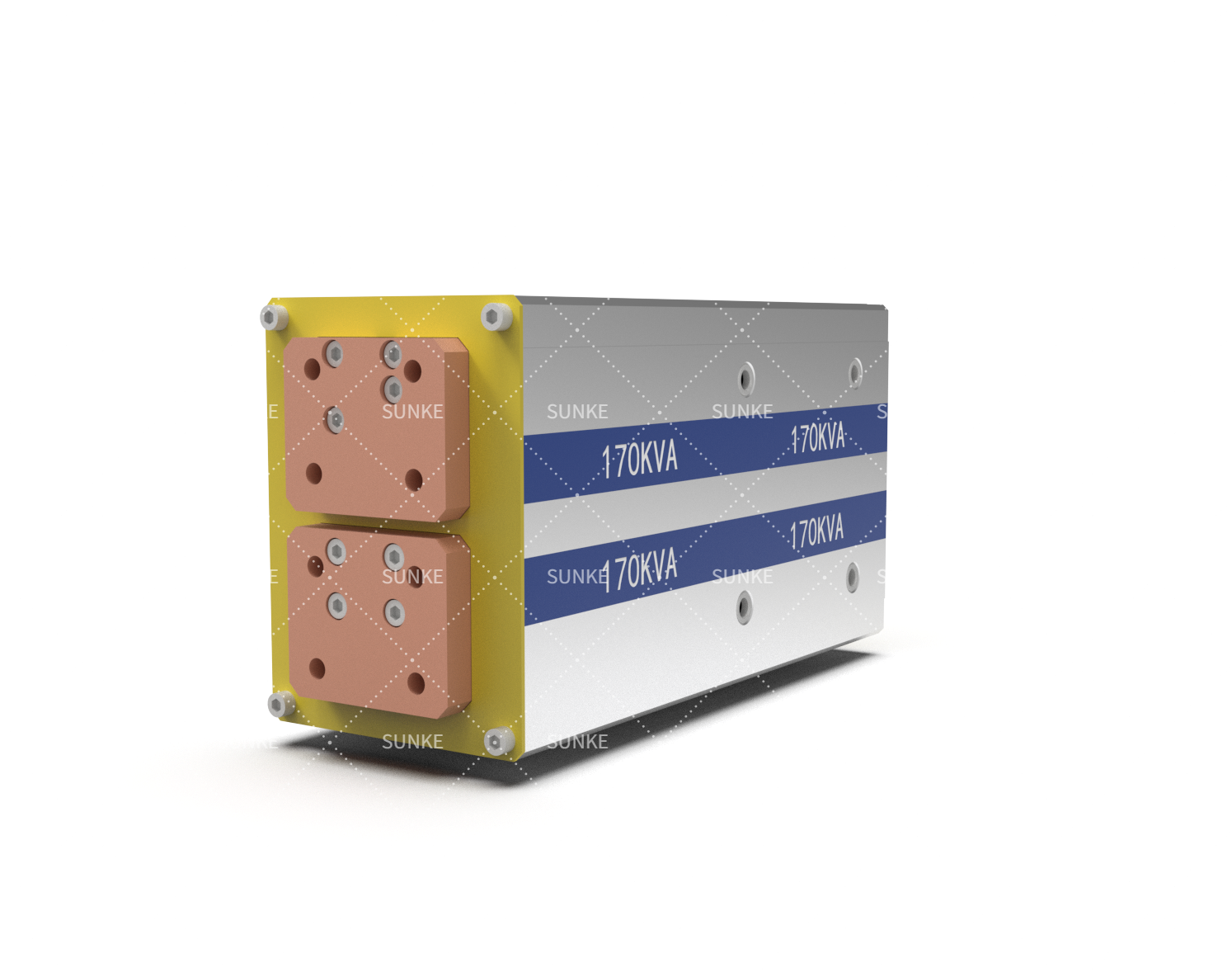
Sunke‘s medium-frequency DC transformer range lists power ratings from 75 kVA to 250 kVA, with options including 75, 100, 130, 140, 160, 170, 220, 225, and 250 kVA. Its published input-frequency specifications include 1000 Hz, 1800 Hz, and 6000 Hz, alongside a PWM 500 V notation. Buyers should confirm the precise meaning of these electrical ratings, the required turns ratio, and the intended operating conditions with the manufacturer’s technical documentation before selecting a configuration.
A welding transformer should ultimately be assessed through application-specific validation. Trial welds, current measurements, thermal checks, and joint-strength testing help establish whether the selected equipment performs as required. Clear acceptance criteria also allow engineering and purchasing teams to compare proposals on verified performance rather than nominal specifications alone.
Conclusion
Transformer turns ratio shapes the electrical conditions available to a resistance welding process, but it cannot be evaluated independently of circuit impedance, power capacity, control settings, and joint requirements. Manufacturers that combine accurate measurements with appropriate transformer sizing can diagnose defects more effectively and avoid equipment mismatches during upgrades.
A well-specified resistance welding transformer, supported by documented technical data and practical validation, gives production teams a sounder basis for maintaining consistent weld quality across changing manufacturing demands.